
Well……not quite. There’s definitely good reasons to calibrate the various axes of a 3D printer. Perhaps a more accurate title would be: “How, when, and why to calibrate your 3D printer.”
Specifically, this article is about the calibration of the ‘steps’ values for each axis, as well as the extrusion multiplier. Other calibrations such as bed-nozzle height, PID tuning, are not going to be discussed.
The art of calibrating stuff.
First, lets consider the purpose of a calibration. Calibration in general terms refers to the act of measurement and adjustment of an instrument to a standard. In terms of 3D printing, it typically refers to the determination of an unknown value to make some aspect of the printer more accurate.
Usually, we want to avoid calibrating multiple variables at once. With 3D printers, this means we want to isolate and calibrate a single axis at a time. If we don’t do this, then errors from one axis can influence the calibrated values on another axis. We’ll touch on this again later, in the “How not to do calibrations” section.
For the mathematically inclined, calibrating multiple axes at once can often result in an underdetermined system. If 5x = 5 then the unknown (x), can easily be determined and equals 1. This represents calibration of a single axis. If 5x + 2y = 7, then there are two unknowns, and the system is underdetermined. x could equal 0.5, and y = 2.25, or x could equal 1 and y could equal 1. There is no way of knowing, and if one of the values is incorrect, then both values are incorrect. This represents attempting to calibrate multiple axes at once.
What calibrations?
There are five adjustable values that are common to all cartesian 3D printers (as well as calibrations for temperature (PID tuning), nozzle to build-plate distance, etc., which won’t be discussed in this article).
- X, Y and Z axis steps are used to define the motor steps per millimetre for each of the main movement axes. (Delta printers also use X,Y and Z (or A, B and C) axes, but these axes don’t correspond directly to the X,Y,Z coordinates of the build plate).
- E axis steps (E-steps) defines how many motor steps per millimetre of filament movement through the extruder.
- Extrusion multiplier – This is a catch-all slicer value to account for different filament hardness, diameter, and other filament specific behaviour.
It is generally accepted that calibration of the X, Y and Z-steps are rarely needed. These values are derived from the drive gear and motor specifications. Consider a drive gear for one axis with 16 teeth, which drives a toothed belt with a pitch of 2mm, using a 1.8º stepper motor with 1/16 microstepping. Each full rotation of the gear moves the belt 32mm, and each full rotation requires 3200 steps (200 full steps * 16 microsteps). Therefore, each millimetre of movement requires 100 steps. A useful calculator for calculating your x, y and z axis steps is available here.
Looking at the definition of calibration mentioned above – determining an unknown value to make an aspect of the printer accurate – shows why we almost never calibrate the X, Y and Z axes. The variables (motor specs, gear, belt) are all well defined and there are no unknowns that need to be determined.
This is also true for the E-steps, which can be determined by the effective radius (centre of the gear to the average “bite” into the filament) of the extruder gear, and the motor and gearing specification. In the early days of 3D printing when extruder gears were not as available as they are now, many users would fabricate their own. Doing so introduced an unknown into the E-axis system, as the effective radius of the hobbed bolt was uncertain. The easiest way to determine the value for the radius of hobbed bolt was to do an E-steps calibration. By feeding a length of filament through the extruder, and comparing the intended length against the extruded length, the E-steps (and in a roundabout fashion the gear radius) could be determined.
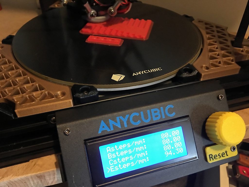
In the last few years, there has been a lot of standardisation in terms of extruder drive gears. These days almost all printers on the market will have a well defined extruder setup, with a known effective gear radius. This is why Bondtech and Prusa specify E-step values for their extruders, and why the common Mk10 extruder often has an E-step value of ~94.3. There is very little need to run an E-steps calibration these days. However, there are still occasional situations when an E-step calibration should be performed.
When to do X,Y, Z and E-step calibrations…
Let’s now look at when you should calibrate your printer’s step values. The first thing to consider is whether you have a good reason to assume that one of the printer’s axes has an incorrect or unknown value? One example would be if you have replaced the extruder gear with a random hobbed gear. In this case, the radius of the extruder gear would be unknown, and you should run an E-steps calibration.
Another situation where calibration is required is if you install new firmware with an incorrect value in it. I recently upgraded a Kossel to Marlin 1.1.9 and found it was overextruding significantly afterwards. E-steps in the firmware was set to 100. A quick calibration suggested that the correct value was around 94.5. I chose to set it to the common mk10 extruder value of 94.3 steps per mm (there is a degree of uncertainty in E-step calibration, so I’ll usually choose a common value in preference to the estimate from calibration).
And when not to do X, Y, Z and E-step calibrations.
There are also many situations where you should absolutely avoid doing calibrations of your printer steps. Some 3d printer users seem to feel that calibration of steps, particular E-steps, is a central part of troubleshooting and should be done as common practice, often as a first resort for trouble shooting. This is often a bad idea.
- You should absolutely avoid trying to set X, Y and Z axes steps using printed objects, such as a calibration cube. The reason for this is that when performing a calibration, you’re working to resolve an unknown. By using a printed object you are introducing more potential sources of error by including the extrusion system in the calibration. If you have an error in your extruder setup, or even just a bit of over or under-sized filament, or even just plastic shrinkage, then the object will be larger or smaller than intended. By using that object to adjust X, Y and Z steps, you’ve added an error into those axes. The goal when performing calibrations is to isolate the one variable that you’re trying to resolve. That means isolating each axis that you think may need calibration so that you don’t transfer errors from one axis into another.
- You should never calibrate steps in response to problems like clogging, random under-extrusion, or bad printer behaviour that just starts one day. The E-steps don’t change as they are still derived from the motor and gear specification, and the effective gear radius. Modifying E-steps in response to clogging has the same problem as calibrating X,Y and Z steps with a printed object. You are introducing unknowns (back pressure, amount of “clogginess”, etc.) into the E-step calibration, which will then be wrong.
- If you are using a printer with well defined steps from the manufacturer, then you should be very careful when replacing the default steps with your own values. In particular, if your values are very different from the default values, then it is quite likely that you have done the calibration incorrectly. If you’re using something like a stock Prusa Mk3 (E-steps are 280 by default), and your calibration suggest an E-steps value of ~400, then your calibrated value is almost definitely wrong. When calibrating steps, be aware that your measurements are not necessarily that precise. You can partly resolve this by running a calibration multiple times, or by increasing the length of measurement. For example, if you run 10mm of filament through the extruder for an E-steps calibration, then your measured E-steps value will most likely be off by quite a few percent. If you run 100mm through, then you’ll probably be within a couple of percent. If you run 1000mm through the extruder, and measure it accurately then your E-steps value will be very accurate (for that filament). There is one important caveat, specifically related to the E-steps calibration (see the next point).
- Don’t assume that your calibration value is perfect. X, Y and Z axes are fairly easy to isolate, and the main sources of error that may affect your calibration are usually related to how accurately you can measure distances. The extruder axis is not as easy to isolate. Remember E-steps are due to the motor and gearing specifications and the effective radius of the extruder gear. However, the filament that you feed through the extruder during calibration can affect the effective gear radius. If you feed a very hard filament, then the extruder may not get as much bite, and the effective radius will be slightly larger. A soft filament may bite deeper, giving a smaller radius. Therefore, when doing an E-steps calibration, don’t consider your value as definitive. It is an estimation and may vary depending on the filament. If the estimated values are close to the default values, then I’d usually stick with the stock E-step, especially with a precise extruder setup like a Bondtech. Fortunately, there is a solution to different filament behaviours, which we’ll cover next.
So what about that extrusion multiplier thing?
X,Y,Z and E steps are all derived from the motor+gear combination for each axis. Usually, these don’t require calibration, and, if they do then the calibration is resolving a single variable, usually the gear radius. In many ways, the extrusion multiplier breaks this concept of calibration for a single variable. It can compensate for filament hardness (and how that affects the effective radius of the extruder gear). It can compensate for variation in filament thickness, and it can compensate for other weird filament behaviour. If you consider that it is a calibration of ‘volume’ of filament extruded, then understanding the calibration is easy. This is one calibration that should be tweaked often and regularly. If you’re really keen you could do it for every filament roll. There are several ways to calibrate this value.
One common method is to print a single wall cube, and measure the wall thickness. I generally avoid this technique. Remember that when calibrating, we want to remove or minimise other sources of error. A single wall has a thickness of around 0.45mm (for a 0.4 nozzle). If your printer is not really precise, and has a bit of wobble in the movement axes, or in the print itself, then that positional error can affect the wall thickness. Most printers have X and Y steps of 80-100, for a resolution of ±0.0125 to 0.01mm. If we assume that the extruder prints perfect 0.45mm lines, and add in 0.01mm of noise from the movement axes, then your wall thickness will measure 0.46mm. This would suggest over-extrusion of ~2%, even though your extrusion is perfect.
A better solution is to use a ‘bulk’ extrusion test. Something with a decent amount of volume like a calibration cube, or the fast under/over extrusion test, that minimises the effect of any noise from other axes. Measuring extrusion across a 20mm thick print means that any error from the movement axes is negligible (20 compared to 20.01mm = 0.05%). Other benefits of using a “bulk” extrusion test include the ability to test extrusion without needing very high accuracy measurement tools. The fast under/over extrusion test doesn’t need any measurement tools at all. Usually, the extrusion multiplier will be within 0.95 to 1.05. If you see values that are a long way outside this range, then you should start looking for other problems, and would be a good reason to check your E-steps.
One point to remember when doing an extrusion calibration though: don’t forget that some materials shrink, sometimes a lot.
Summary (TL:DR)
- X, Y, Z and E-step calibrations should be carried out rarely. Usually only in response to hardware and firmware changes.
- Consider the unknowns that you are calibrating for. If there are no unknowns and the manufacture has specified a reasonable steps value, then you should consider whether you are replacing a good, default value, with a potentially worse estimation.
- Extrusion multiplier can be calibrated regularly, even on a spool by spool basis. It accounts for filament hardness, diameter variation and other weirdness. It’s the first thing to look at if you are confident your printer is behaving, but you’re seeing under or over extrusion.
- Don’t fret the calibrations. They are important, but are also rarely needed. I run 4 different printers and print accurate parts with small tolerances. I have run an E-steps calibration once. I’ve never run an X, Y or Z calibration. I run extrusion multiplier calibrations regularly. Not for each spool, but definitely if I get a new spool that looks like it gives under or over extrusion.
- Print lots, and don’t calibrate your E-steps every day. You’ll go blind. 😀