First update in a while. I’ve been very busy and haven’t had a chance to blog much lately. Today, I’ll be showing a quick and easy way to fix up problematic CT Scan 3D reconstructions (which may also be useful for other 3D reconstruction techniques). When scanning bones using a CT scanner, you’ll often get a good representation of the outside surface of the bone, as well as any voids and cavities inside the bone. In many cases, the internal void may lie fairly close to, or connect to, the external surface, which often results in the surface of the void connecting to the external surface. This represents a challenge for 3D printing. The files may be watertight, but are essentially thin skins, which are fragile and challenging to print.
The common approach to deal with this type of problematic topology is shrinkwrapping, where a new mesh is created around the original bone mesh and drawn inwards until it meets the outermost skin, passing over the small gaps that connect the internal and external surfaces and forming a single watertight surface that approximates the original external surface.
Shrinkwrapping is not a common tool in 3D apps. Blender and Rhino can do it via scripting. Meshmixer can also do it after a fashion, using the ‘Attract’ tool. However, there is a simple process in Meshmixer which can do a very similar job.
The Process
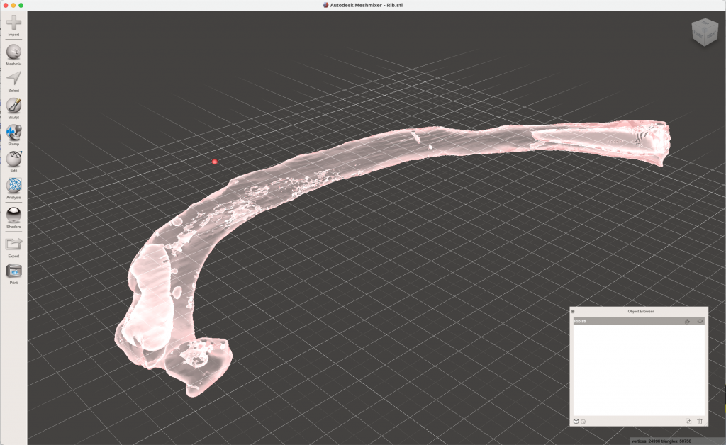
Load your CT scan into Meshmixer and have a look at it to assess the void structure. The rib pictured below, for example, has several major voids, all of which are connected to the external surface.
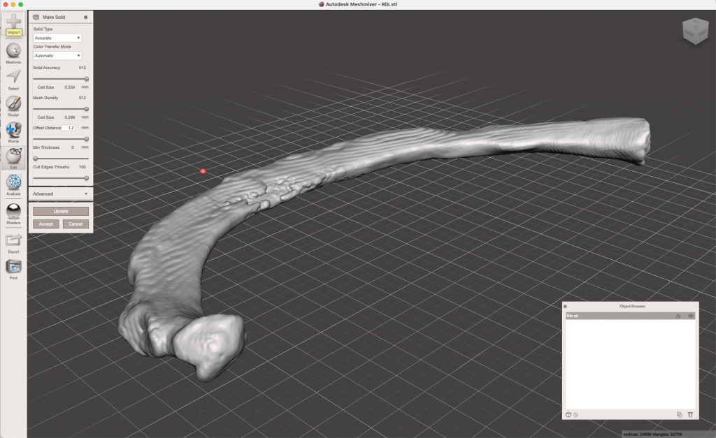
Now, we’ll create a new mesh with a slight offset outwards. In this case we’re offsetting the mesh outwards by 1.2mm using the “Make Solid” tool. Use a high value for Solid Accuracy and Mesh Density to preserve the original shape. This process closes any existing holes in the mesh and separates the internal from the external surfaces. I usually start with a small offset (0.5 mm or so) and increase the value as required until the internal shells are isolated. If I feel it requires too large a value, and the offset process starts damaging the original shape, then I’ll switch to other techniques (boolean infilling, etc)
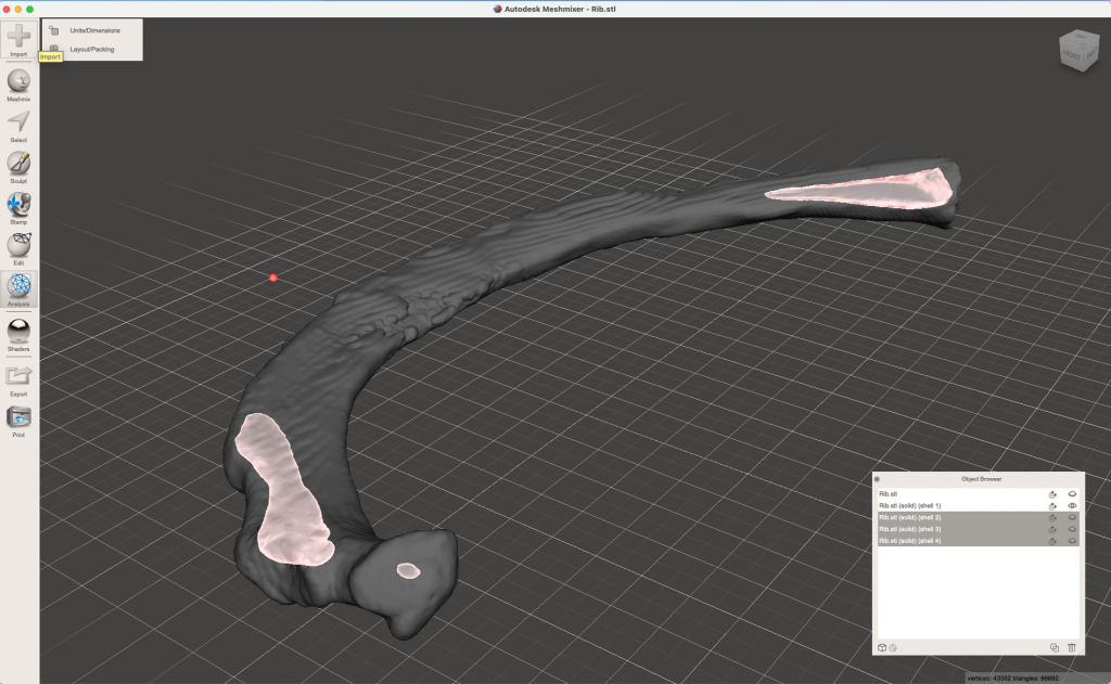
Following the offset process, use the “Separate Shells” to extract the internal surfaces and delete them.
Then, reconstruct the original mesh, by using the “Make Solid” tool again, but this time using a negative offset of the same magnitude as before. This reconstructs the original model, using only the external surface. You can view both the original mesh and the reconstruction at the same time to assess whether there are any errors due to the offsetting.
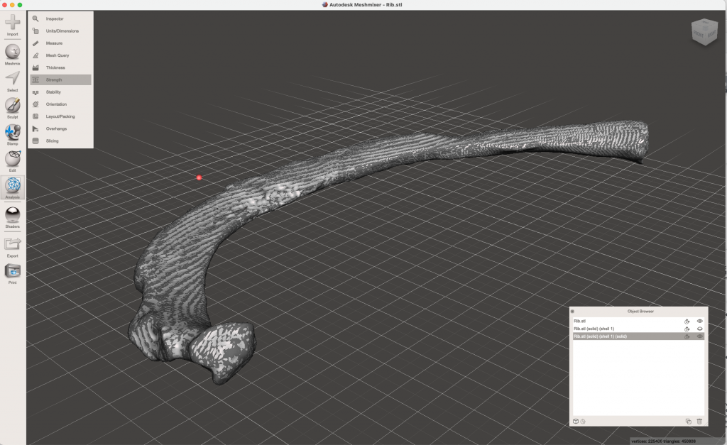
The “Make Solid” tool used in this way typically generates a much higher resolution mesh than the original. To get it back down to size, use the “Select” -> “Reduce Mesh” tools to achieve a sensible triangle count. Then export your repaired mesh and enjoy how easy it is to 3D print the new file.
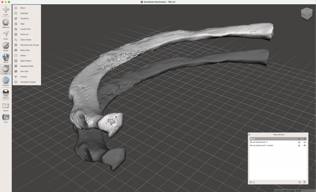
Example of the original, holey mesh, and the reconstructed mesh ready for 3D printing. 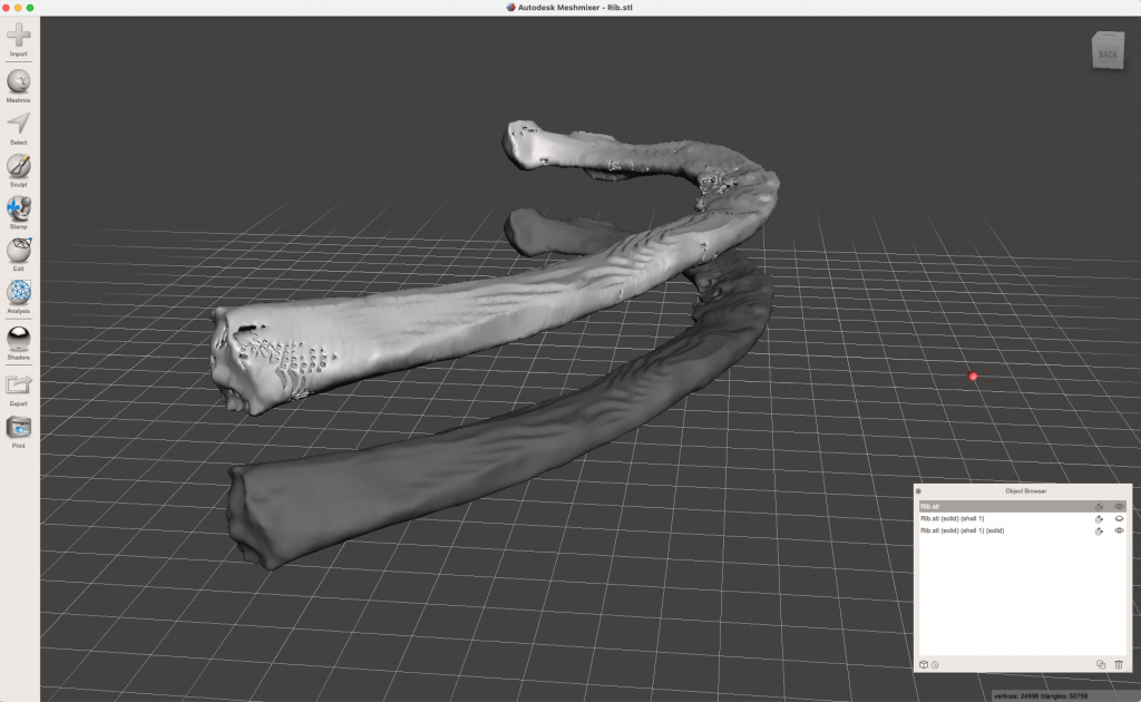
Another view of the original, holey mesh, and the reconstructed mesh ready for 3D printing.