A sediment trap for lake research is an interesting thing to design. In some cases a trap can be incredibly simple, essentially being a tube submerged in a lake. However, many lakes have low sedimentation rates. To identify seasonal differences in sedimentation may require collection of a lot of sediment over a short time. This means that a simple tube is often not the best option, and funnels are required to capture sufficient sediment.
There are a handful of commercial sediment traps on the market, but many projects have limited budgets and require DIY solutions. DIY sediment traps present challenges as numerous components – funnels, sampling tubes, frame, etc – all have to be connected in a way that gives a smooth surface from the top of the funnel to the sample collection tube.
This sediment trap design takes advantage of 3D printing to fabricate the complex components required. It is designed to be deployed in a lake that has a sediment deposition rate of around 1mm/year, and should collect around 8 mL of sediment each 3 months. Non 3D printed parts are simple components available from a hardware store, consisting of M5 stainless bolts, 90mm PVC stormwater pipe, and pipe brackets attached to a frame of some sort.
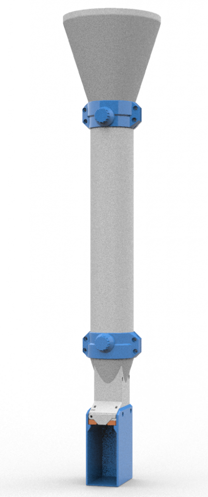
A 3D printed 200 mm Ø upper funnel is coupled to a 90mm PVC tube with a 3D printed mechanical clamp. The 90mm PVC tube is 400-500mm long to minimise turbulence affecting the sample (Bloesch, J. & Burns, N., 1980), and to provide a place to attach the frame. At the base of the tube is a second funnel going from 90mm to 12mm. This funnel guides sediment to the sample tube. The sample tube is threaded onto a sliding plate. The sliding plate minimises disruption of the sediments by avoiding the need to unscrew the sample tube with several litres of water in the funnels pushing down on the sample.
Both funnels are quite tall to keep the sides as near to vertical as possible. The upper funnel uses the full build envelope of a Prusa Mk3 printer (210 mm). Each funnel has a lip around the base section that is coupled into the clamp. Funnels are printed in ASA, and then sanded smooth, followed by a cold acetone vapour treatment to smooth the funnel surface. The upper funnel has a lip that extends over the edge of the PVC tube, whereas the lower funnel begins just outside the inner surface of the PVC tube.
Each clamp is printed in PETG and is held in place with four M5 x 30mm stainless bolts. The clamps are mechanically fixed to the funnels by the lip on each funnel, and compression clamped to the PVC. On each clamp is an M16 threaded section that fits a plastic screw bung. The bung is screwed through the clamp, and then through the side of the PVC (via a 12.9 mmØ hole). This bung serves two purposes. It serves as a mechanical lock that links the clamp to the PVC pipe, and it allows the user to drain the upper funnel and PVC tube as the trap is lifted out of the water.
There are two designs for the sliding tube holder, holding either a 15ml and 50ml centrifuge tube. The slides and tubes are contained within a frame that protects the sampler tube. As a slide is removed, it closes off the port at the bottom of the funnel so that water in the funnel can’t drain into the sample tube potentially disturbing the sediments. The water in the funnel then drains once the slide is removed.
The modular nature of the sampler means that alternative or replacement parts are easy to add, without having to rebuild the entire unit. Total cost of this sampler should be around $200-300 dollars. There’s around 800gm of plastic in each trap, and the connecting frame, PVC tubes and nuts and bolts.
You can download files for it from here.
Bloesch, Jürg & Burns, N.. (1980). A Critical Review of Sediment Trap Technique. Schweizerische Zeitschrift für Hydrologie. 42. 15-55. 10.1007/BF02502505.